Source: YOKOGAWA
Prior to any type of further gas treatment, a gas recovery system (GRS) is required. Particularly in Europe and the United States most GRSs were installed based on positive economic situations where the period of repayment was considerably short to justify investment, but due to increased environment responsibility and regulations, there is increased interest in flare reduction.
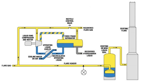
GRS are increasingly installed to comply with local regulatory limits on flaring and must be sized to conform to any such limits . Actual loads on FGR systems will vary widely and must be designed to operate over a wide range of dynamically changing loads over time. The figure on the right shows a schematic diagram of an GRS.
The GRS is installed upstream of a flare header to collect some or all of the flare gas before it reaches the flare header. A knock-out (KO) drum (compressor suction/inlet drum) to remove suspended vapor from gas is installed upstream of the FGRS which is in turn upstream of a Liquid Seal vessel (LSV) located just before the flare header.
The KO drum and the flare network typically operate at low pressure close to atmospheric pressure which is a hazard in itself because if flow of flare gas is stopped for some reason the GRS compressors suck air into the flare header and cause an explosive mixture of gases into the plant. The liquid seal drum/vessel provides safety against this backward air leakage and allows build-up of positive pressure in the flare header. It is crucial that the LSV is properly designed and sized to handle the changes in flow and transitions safely from the normal flare gas flow rates to any emergency flare gas flow rate.